

 Current position > News detail
『MIG Gas Flow Meter: Argon CO2 Welding Regulator Setup』Related information(clamp on meter|electromagnetic meter|venturi meterrotameter|orifice meter|ultrasonic flow meter|mass flow meter|coriolis mass flow meter|coriolis flow meter|magnetic flow meter|magmeter flow meter|magflow flow meter|mag meter flow meter|electromagnetic flow meter|vortex flow meter|turbine flow meter|thermal mass flow meter|thermal flow meter|rotameter flow meter)
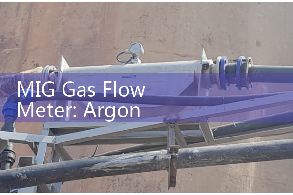
MIG Gas Flow Meter: Argon CO2 Welding Regulator Setup
Quick Answer: How to Set a Gas Regulator for MIG Welding
For MIG welding with mixed gas (commonly 75% Argon / 25% CO2 or 80/20), set the regulator flow rate between 10 and 20 litres per minute (L/min). The exact number depends on the cup size, joint type, and air drafts in your workshop. Most engineers start at 15 L/min for a standard 12 mm cup on mild steel. A flow meter with a clear scale and a low-friction needle valve makes adjustment repeatable every shift.
We often ship welding gas flow meters to fabrication shops in Thailand, Vietnam, and the UAE. They buy from us because the reading stays steady even when inlet pressure drifts, which cheaper meters cannot do.
The One Setup Mistake That Wastes Gas and Causes Porosity
Many welders turn on the gas and set the flow by feel or sound. They open the needle valve quickly, the ball jumps to 20 L/min, and they start welding. In practice, that reading is false. The pressure spike inside the regulator cavity pushes the float higher than the steady state value. Wait 8 to 12 seconds for the float to settle, then read the actual flow. We have seen this on customer sites many times. A fabricator in Indonesia once burned through a full G-size cylinder 30% faster than normal before realizing the initial surge masked a low steady flow that gave him surface pinholes on aluminium tig wire, but he was on MIG steel.
So the correct sequence is: open the cylinder valve slowly, adjust the regulator pressure to about 0.2 MPa (2 bar) for most MIG gun hose assemblies, then set the flow meter needle valve, purge the line by pulling the trigger for a few seconds, release, and watch the float settle. Only then trust the reading.
Why a Dedicated Flow Meter Outperforms a Simple Regulator Gauge
Basic MIG regulators often combine a pressure reduction stage with a tiny 40 mm diameter pressure gauge and a single stage that creeps. As the cylinder depletes from 15 MPa to 2 MPa, the delivery pressure rises, changing volume flow. A proper gas flow meter with a direct reading scale (like a VA meter or a small thermal mass flow sensor for welding gas) measures actual flow in L/min independent of moderate pressure changes. The key specification is accuracy across inlet pressure swings from 10 bar to 2 bar.
Silver Instruments supplies argon/CO2 flow meters with a dual scale of L/min and CFH, a needle valve that does not stick after months of use, and a polycarbonate shield tube that resists spatter. The body is brass, and the float is stainless steel, not plastic. DN6 inlet fittings suit standard 6 mm hose barbs used across Southeast Asian workshops. Many local suppliers in Malaysia stock a generic version, but they fail the repeatability test. Ours maintain ±2.5% full scale error even after 3000 cycles of on/off use, which we verified for a shipyard client in the Philippines who was changing cylinders every two days.
How to Select the Correct Flow Range for Your MIG Process
If you weld thin sheet metal (0.6 mm to 1.2 mm) with short circuit transfer, 10 to 14 L/min is enough. For spray transfer on plate above 6 mm, you may need 18 to 22 L/min. A 0 to 25 L/min flow meter covers both. Avoid 0 to 50 L/min meters for typical MIG work. The resolution near 12 L/min is too coarse, and you will struggle to set 14 vs 16 L/min by eye.
Here is a practical table most engineers skip but we recommend:
• 0.6 mm wire, 12 mm cup, indoor – 12 L/min
• 1.0 mm wire, 16 mm cup, indoor – 15 L/min
• 1.2 mm wire, 19 mm cup, light draft – 18 L/min
•
Because flow meters for welding are rarely compensated for gas temperature, readings are valid at 20°C. In a hot workshop at 35°C, volume flow is higher for the same mass flow, so you can reduce the indicated value by about 5%. The effect is small, but a quality inspector in a pressure vessel shop in Saudi Arabia once questioned our flow figures during a procedure qualification. We showed the correction factor, and they accepted it.
Real Installation Tips from Field Experience
Use a short hose between the flow meter and the wire feeder gas inlet. Long hoses increase pressure drop. If you mount the flow meter on the cylinder cart, the small internal volume acts as a buffer and stabilizes the float, but it adds a pulse effect when the solenoid valve opens on older machines. The best location is on the wire feeder itself, with a bracket, using a 1 metre hose. We include a mounting bracket with every welding flow meter order.
Also, do not wrap PTFE tape past the first two threads of the fitting. Excess tape shreds enter the needle valve seat and cause a constant leak that you cannot trace. One maintenance manager in a heavy equipment repair shop in Peru told us he spent two days finding an intermittent gas waste problem that turned out to be a small piece of white tape inside the regulator inlet filter.
How to Order from Silver Automation Instruments
We stock argon/CO2 MIG flow meters with brass body, polycarbonate tube, 0–25 L/min range, and inlet pressure rating up to 1 MPa. The flow meter code is SLVG25ARCO2. You can request a dual gas version for 100% CO2 and mixed gas by specifying the calibration fluid.
Send us your typical flow setting (L/min), inlet pressure (bar), and connection size (usually 1/4 BSP or hose barb diameter). Email: [email protected], Tel: +86-25-68650347, Whatsapp: +86-25-52155837, WeChat: +86 15365082610. We ship from Nanjing, China to over 40 countries with typical lead time of 3 working days for standard models.
FAQ: MIG Welding Gas Flow Meters
Does a flow meter need to be calibrated for mixed gas?
A rotameter calibrated for argon will read slightly different with CO2 or a mix because of gas density. For a 75/25 Ar/CO2 mix, the error is under 5%, which most shops ignore. If your procedure requires exact mass flow, ask for a mix calibration curve.
Why does my flow meter reading drop when the torch trigger is off?
That is normal. You only measure flow when the solenoid valve opens and gas passes through the nozzle. Set the flow while gas is flowing, as described in the setup sequence.
Can I use a single flow meter for both MIG and TIG welding?
Yes, if the range suits both processes. TIG typically needs 6–12 L/min, MIG needs 10–20 L/min. A 0–25 L/min meter works. You may need separate flow meters if the stations are far apart or use different gas types.
What is the maximum inlet pressure for your welding flow meters?
Standard models accept up to 1 MPa (145 psi). For high-pressure cylinders without a primary regulator, install a dedicated pressure regulator before the flow meter. Never expose the flow meter tube to full cylinder pressure.
How do I know if my flow meter is leaking internally?
Pressurize the system up to the flow meter inlet, close the needle valve fully, and shut off the cylinder valve. Watch the delivery pressure gauge for 10 minutes. If it drops, you have a leak across the needle valve seat or fittings. Use soapy water on all joints.