

 Current position > News detail
『ABB WaterMaster Flow Meter Manual: Remote terminal wiring and loop testing.』Related information(clamp on meter|electromagnetic meter|venturi meterrotameter|orifice meter|ultrasonic flow meter|mass flow meter|coriolis mass flow meter|coriolis flow meter|magnetic flow meter|magmeter flow meter|magflow flow meter|mag meter flow meter|electromagnetic flow meter|vortex flow meter|turbine flow meter|thermal mass flow meter|thermal flow meter|rotameter flow meter)
ABB WaterMaster Flow Meter Manual: Remote Terminal Wiring and Loop Testing
Quick Answer: Remote terminal wiring on an electromagnetic flow meter connects the power supply, the 4-20 mA HART output, and the pulse or digital outputs. A loop test forces the output to 4 mA, 12 mA, and 20 mA so you can confirm the PLC or DCS reading. Silver Instruments supplies DN15 to DN2000 electromagnetic flow meters with the same remote terminal wiring logic used on ABB WaterMaster installations.
Why Remote Terminal Wiring Matters
Most electromagnetic flow meters split into two parts. The sensor sits in the pipe. The transmitter reads the electrode signal and drives the output loop. Remote terminal wiring brings all power and signal wires to one location inside the transmitter. This is common on water treatment plants, desalination lines, and food and beverage skids.
In practice, many technicians see the same terminal block layout. Power terminals sit on the left. Signal output terminals sit in the middle. Pulse and digital output terminals sit on the right. ABB WaterMaster meters follow this general pattern. Our SIL-EMF series magnetic flow meters also use this block layout. You can find similar guidance in the ABB WaterMaster flow meter manual.
Remote Terminal Wiring Steps
Shut off power before you open the transmitter cover. Use a 2.5 mm slotted screwdriver for the terminal screws. Each terminal accepts 0.5 mm2 to 1.5 mm2 stranded wire. Use shielded twisted pair cable for signal and pulse outputs.
Wire the power first. For 24 V DC units, connect positive to the L+ terminal and negative to the N- terminal. For 85-265 V AC units, connect live to L and neutral to N. The earth terminal must go to a clean plant ground. Do not skip the ground wire. Magnetic flow meter accuracy drops if the ground loop is noisy.
Wire the 4-20 mA HART output next. Connect the positive side to terminal I+ and the negative side to terminal I-. The loop is active or passive depending on the transmitter version. Your PLC analog input card often provides the 24 V DC loop supply. If the PLC input is passive, you need an external 24 V DC supply in series with the loop.
Pulse output uses terminal P+ and P-. This can drive an electromechanical counter or a PLC high speed input. Set the pulse width from 0.5 ms to 100 ms. RS485 Modbus output uses A and B terminals. Use a 120 ohm terminating resistor at the last device on the bus.
Loop Testing the 4-20 mA Output
Here is the thing. A correct wiring job does not guarantee a correct loop reading. You need to verify the current. Place a 250 ohm resistor in series with the loop. Set your multimeter to DC voltage across the resistor. A 4 mA signal reads 1.00 V DC. A 12 mA signal reads 3.00 V DC. A 20 mA signal reads 5.00 V DC.
Set the transmitter to forced output mode. You can do this from the local keypad or a HART handheld. Force 4 mA. Check the PLC display. Force 12 mA. Check the PLC display again. Force 20 mA. Confirm the display matches the flow span. If the PLC shows 25 percent flow at 12 mA on a 0-100 m3/h span, the scaling is correct.
Do the same test for the pulse output. Use a frequency counter or a PLC high speed input. At a known flow rate, the pulse frequency should match the pulse rate. Most SIL-EMF transmitters allow pulse rate from 0.001 to 1000 pulses per liter.
Common Site Failures During Loop Testing
We hav
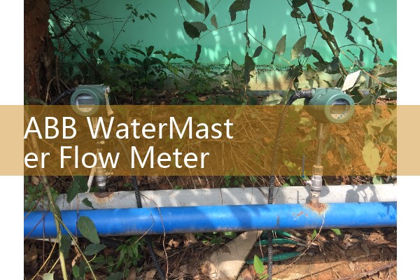
Most engineers skip this part. Power wiring and signal wiring can run in the same conduit on short runs. But longer runs pick up EMI. Keep signal cables separate from AC power cables. Use a minimum gap of 200 mm. Use a shielded cable with the shield grounded at one end only.
An Indonesian chemical plant had a loop test fail because the terminal screws were not tightened after a cold startup. The 4-20 mA signal dropped to 0 mA every few minutes. Retorque the screws to 0.5 Nm and the problem disappeared.
SIL-EMF Series Options for Remote Terminal Wiring
Silver Instruments supplies the SIL-EMF series electromagnetic flow meter for remote and compact mounting. Sizes cover DN15 to DN2000. Liner options include PTFE, neoprene, and polyurethane. Electrode options include 316L, Hastelloy C, and titanium. Accuracy is 0.5 percent of reading for flows above 0.5 m/s. The transmitter accepts 24 V DC or 85-265 V AC. Outputs include 4-20 mA HART, pulse, frequency, and RS485 Modbus.
For hazardous areas, the remote version can be supplied with ATEX Zone 1 approval. Flameproof cable glands are required. The terminal compartment stays separate from the electronics compartment. This makes wiring easier in tight panels.
Because many plants already use ABB WaterMaster meters, the SIL-EMF remote terminal layout is designed to be familiar. You can often replace a failed meter with a SIL-EMF meter without redesigning the panel wiring.
FAQ
Question: Can I use the same 24 V DC supply for power and loop output?
Answer: Yes, but only if the power supply has enough current capacity. Add up the meter power draw and the loop load. Keep a separate fuse for each device.
Question: What is the minimum cable size for remote terminal wiring?
Answer: Use 0.5 mm2 stranded copper wire for short runs. For runs over 100 meters, use 1.0 mm2 or 1.5 mm2 to reduce voltage drop.
Question: How do I test a passive 4-20 mA output?
Answer: Connect a 24 V DC supply in series with a 250 ohm resistor and your multimeter. The current must stay stable at 4 mA, 12 mA, and 20 mA during forced output.
Question: Does the SIL-EMF remote transmitter fit an ABB WaterMaster sensor?
Answer: No. The SIL-EMF transmitter is designed for Silver Instruments sensors. It is not a direct electronic replacement for ABB sensors. If you need a full meter replacement, send us the flange standard, liner, electrode, and flow range.
Question: What flow range should I specify for loop testing?
Answer: Send us your normal and maximum flow in m3/h or kg/h. Also send pipe size in DN, fluid conductivity in µS/cm, pressure in bar, and temperature in °C. We will set the 4 mA and 20 mA span before shipment.
For a SIL-EMF quote, send us your pressure in bar, temperature in °C, pipe size in DN, flow range in m3/h, and fluid type. You can reach Silver Instruments by Tel at +86-25-68650347, by Whatsapp at +86-25-52155837, or by WeChat at +86 15365082610. Our website is flow-meter.com.au.