


『Coriolis Flow Meter Wiring Diagram: Connecting 4-20mA Outputs to Automation PLCs』Related information(clamp on meter|electromagnetic meter|venturi meterrotameter|orifice meter|ultrasonic flow meter|mass flow meter|coriolis mass flow meter|coriolis flow meter|magnetic flow meter|magmeter flow meter|magflow flow meter|mag meter flow meter|electromagnetic flow meter|vortex flow meter|turbine flow meter|thermal mass flow meter|thermal flow meter|rotameter flow meter)

Coriolis Flow Meter Wiring Diagram: Connecting 4-20mA Outputs to Automation PLCs
Application Note for Silver Instruments CMF Series Coriolis Flow Meters
Quick Answer: A Silver Instruments Coriolis flow meter with a 4 to 20 mA output connects to a PLC analog input with two wires. Use a shielded twisted pair cable and check whether the output is active or passive. For an active output the meter supplies loop power, for a passive output add a 24 V DC loop supply and keep the loop resistance above 250 ohm for HART.
Terminal Layout on a Silver Instruments Coriolis Flow Meter
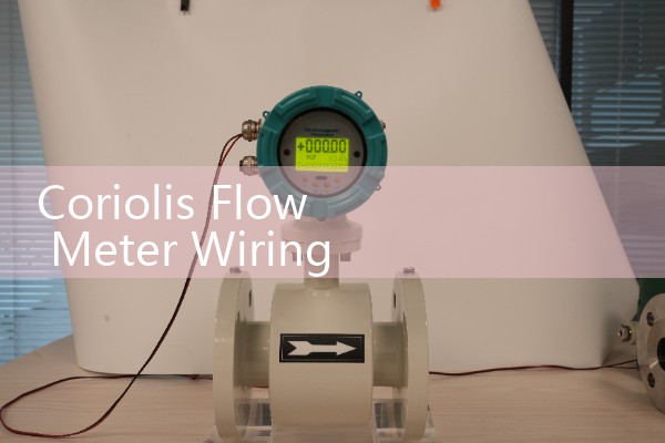
The CMF series Coriolis flow meter has a two chamber wiring compartment. One chamber holds the power terminals. The other chamber holds the signal terminals. A typical terminal block shows 24V, 0V, IO1+, IO1-, IO2+, IO2-. IO1 is the primary 4 to 20 mA output. IO2 can be a pulse output or a second 4 to 20 mA channel. Check the model code and the wiring diagram inside the terminal cover. Silver Instruments ships every CMF Coriolis meter with a paper diagram and a QR code link to the PDF.
For a standard active 4 to 20 mA output, the flowmeter sources current to the PLC analog input. The PLC input channel must be set to current mode. Most engineers skip this part and then wonder why the signal reads zero. In practice, a Siemens S7-1200 or Allen Bradley CompactLogix analog card may need an external shunt resistor if the channel is voltage only.
Two Wire Active Loop Wiring
Connect the meter terminal IO1+ to the PLC AI positive terminal. Connect IO1- to the PLC AI negative terminal. Use 0.5 mm² to 1.5 mm² shielded twisted pair cable. The shield drain wire connects to the PLC ground terminal only. Leave the shield floating at the flowmeter end. This rule avoids ground loops on sites with poor earthing.
If the PLC analog input is isolated, the loop still works because the current flows through the shunt resistor. The signal current is 4 mA at zero flow and 20 mA at full scale. The loop update time on the CMF series is configurable from 100 ms to 1 second. For a fast batching process, set 100 ms. For a slow blending loop, 500 ms is enough.
Passive Loop Wiring and Power Supply
Some CMF series models are ordered with a passive 4 to 20 mA output. In this mode the flowmeter does not supply loop power. Wire a 24 V DC power supply in series with the loop. The positive terminal of the power supply goes to the meter loop positive. The meter loop negative goes to the PLC AI positive. The PLC AI negative returns to the power supply negative. This is a standard two wire passive current loop.
We have seen this on customer sites many times where a panel already has a common 24 V DC bus. The passive output works well there. Make sure the power supply is not the same one that drives contactors or solenoid valves. Inductive spikes cause the loop reading to jump.
Cable and Grounding Rules
Signal cable distance for 4 to 20 mA can reach 300 metres with 0.75 mm² copper. If the run is longer, use 1.5 mm² cable or add a signal isolator. Keep the signal cable at least 200 mm away from VFD cables. Do not run signal and motor cables in the same tray. When the tray crosses a power cable, cross at 90 degrees.
Shield grounding matters more than most engineers think. A shield grounded at both ends can carry circulating current. That current adds noise to the 4 to 20 mA signal. This problem is common on our support calls. Another common issue is a missing 250 ohm resistor in a HART loop.
HART and 4 to 20 mA on the Same Pair
The CMF series supports HART protocol on the primary 4 to 20 mA output. The HART signal is a frequency overlay and does not affect normal current readings. You can configure the meter with a HART handheld or a HART modem. For HART co
Loop Check and PLC Scaling
Zero flow on the CMF series gives a 4.00 mA signal. Full scale flow gives a 20.00 mA signal. In the PLC, map the raw value to engineering units. For a CMF-025 meter with a 0 to 10 t/h range, 4 mA equals 0 t/h and 20 mA equals 10 t/h. The slope is 0.625 t/h per mA. The offset is negative 2.5 t/h. In a Siemens S7-1200, the raw value 0 corresponds to 4 mA and 27648 corresponds to 20 mA.
Most engineers skip the loop check. So we always say: simulate 4 mA, 12 mA, and 20 mA at the PLC card. Verify the readings. Then enable closed loop control. This catches reversed polarity and wrong channel configuration. It also shows bad terminals.
Common Wiring Mistakes on Site
Reverse polarity is the most common issue. The 4 to 20 mA signal will read negative or fault. The second issue is using a two wire cable without shield. The third is terminating the shield at the meter side and the PLC side. Each problem has a simple fix. Double check the terminal label before powering the meter. Measure the loop current with a multimeter in series. The DC voltage across a 250 ohm shunt should be 1.00 V at 4 mA and 5.00 V at 20 mA.
Recommended Models for PLC Integration
For water and wastewater plants, the CMF series DN15 to DN100 covers most flows from 0.1 t/h to 120 t/h. For food and beverage, use the CMF series with hygienic Tri-Clamp connections and the same 4 to 20 mA output. For chemicals, select Hastelloy C or 316L wetted parts and add a HART modem if you need remote setup. A paint manufacturer in Southeast Asia used a CMF-025 with a 4 to 20 mA output to a Siemens S7-1200 and cut batch time by 12 percent. The wiring was two wires plus shield, no extra barrier.
If your PLC needs volume flow in m3/h, tell us the fluid density. The CMF series measures mass flow, volume flow, density, and temperature at the same time. The 4 to 20 mA output can be mapped to any of these variables. For hydrocarbons, use mass flow in kg/h. For water, volume flow may be more useful.
FAQ
Can I connect a Coriolis flow meter 4 to 20 mA output directly to a PLC analog input?
Yes. The CMF series 4 to 20 mA output is compatible with most PLC analog cards that accept current inputs. Set the card to 4 to 20 mA mode. If the card only accepts voltage, add a 250 ohm shunt resistor.
Does the Silver Instruments CMF series output active or passive 4 to 20 mA?
Both modes are available. The standard version uses an active output. The passive version is common for panel buses with a shared 24 V DC supply. Check your model code before wiring.
What cable size should I use for the 4 to 20 mA signal?
Use 0.5 mm² to 1.5 mm² shielded twisted pair cable. For distances up to 300 metres, 0.75 mm² copper is enough. Keep the cable away from VFD drives and motor cables.
Can I use the same two wires for HART and 4 to 20 mA?
Yes. The HART signal rides on the same pair. Keep the loop resistance between 250 and 1100 ohm for HART communication. The normal current signal stays clean.
How do I scale the 4 to 20 mA signal in the PLC?
Set 4 mA to the zero flow value and 20 mA to the full scale flow value from the meter configuration sheet. Then verify with a 12 mA test. The midpoint should read 50 percent of full scale.
For a wiring diagram specific to your PLC or a quote, send us your fluid, flow range (kg/h or t/h), pressure (bar), temperature (°C), pipe size (DN), and PLC brand. Contact Silver Instruments. Tel: +86-25-68650347. Whatsapp: +86-25-52155837. WeChat: +86 15365082610.
 Hot Product
 Related AD